Displaying 1-2 of 2 result(s).
Introduction
-
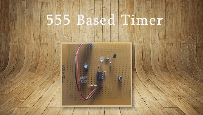
In this circuit IC 555 is used as monostable multivibrator. When switch SI push pin no. 2 of IC 555 go to low which is normally high. At that time pin no. 3 go to high with respect to time constant provide by RC network on pin no.6 and pin no. 7. This time duration can be changed with the help of potentiometer P1. When output of IC at pin 3 go high transistor Tl get base biasing through resistor R2 & Tl conduct So that relay get ground connection through Tl & it will turn ON or OFF device which is connected through relay.
|
PART LIST FOR 555TIMER CIRCUIT
|
|
R1,R2,R4
|
- lOK-Brown Black Orange
|
Tl
|
-BC54&-NPN Transistor
|
|
R3
|
-1K- Brown Black Red
|
Dl
|
-1N4148
|
|
PI
|
- 100K/1M Horizontal Preset
|
D2-D5
|
-1N4QQ7-Rectifier Diode
|
|
CI
|
-100uT/l:6V-EleerFelytic Cap.
|
Ul-
|
-NE555 Timer IC
|
|
C2,C4
|
-0.01 uF-10KPF-103-Dtsk type
|
LI,L2
|
-5MM Red/Green LED
|
|
C3
|
-1OOOu.F/1 6V- Electrolytic Cap,
|
RL1 -
|
12 V, ICO PCB Mount Relay
|
Parts should be soldered on PCB in following order. First smallest height parts that is all resistor, diode and then transistor , PF and LED. Last solder relay and electrolytic capacitor. See the polarity of LED, electrolytic capacitor and diode before soldering.
What is Included?
-
Project Definition ( by Email )
Project Circuit Diagram ( by Email )
Project Report ( by Email )
Project ( by Courier)
23822384


